LessLoss DAC 2004 Mk.II W/ REGA Mod Transport
Listed · 292 Views
This listing has ended.
Listings Similar to LessLoss
Time Left: Listing Sold
This listing has ended.
| Condition | |
| Payment methods | |
Contact seller after sale to pay viaVISA/Mastercard | |
| Ships from | Los Angeles, CA, 90077 |
| Ships to | United States and Canada |
| Package dimensions | unspecified |
| Shipping carrier | UPS |
| Shipping cost | |
| Original accessories | Manual |
| Research Pricing |
DAC 2004 MkII Battery Powered & matching Rega Planet (modified for Less Loss DAC) in matching Silver, serviced with new set of 12 volt batterys and Rega Transport aligned and serviced:
This is a matching pair as new the world renown battery DAC & matching REGA Top Loading Transport as new (see pictures):
See Rave Review in Positive Feedback ISSUE 35 on the Mk-i the MK-II is even better:
https://positive-feedback.com/Issue35/lessloss_dac.htm
Danny Kaey sums it all up:
...The Greats…
I tossed out the phrase Giant Slayer earlier—some believe this is simply not possible; they will claim that in the end, only companies which have the appropriate wherewithal are in fact capable of designing and implementing a reference level component. While there are certain elements of truth in that premise, I have to disagree at the fundamental level. It was none other than Nikola Tesla who brought us AC or Alternating Current the foundation for our modern day lives. It was none other than Sir Isaac Newton who defined the laws of universal gravitation. Last I checked those were all individual men sans corporate baggage and bean counters that revolutionized our way of life. Is the LessLoss DAC 2004 therefore a revolutionary, groundbreaking product? Certainly not within the context of the former gent’s monumental accomplishments.
I do however believe that LessLoss has in fact created a reference quality product for far less than perceived reference price. Given that Lithuania has quickly established itself as leaders in the technology sector, in particular laser production (as it turns out, many of the leading worldwide companies and labs utilize laser assemblies from Lithuania), it comes as no surprise that Vil and Liudas have a winner on their hands. To those who wish giant killing performance at real-world prices, the LessLoss DAC 2004 is the pick. Most highly recommended! Danny Kaey
DAC 2004
Retail: $4400 US
-------------------------------------------------------------------------------------------------------------------------------
See: Sixmoons.com Rave review @
http://www.6moons.com/audioreviews/outside3/outside.html
------------------------------------------------------------------------------------------------------------------------------
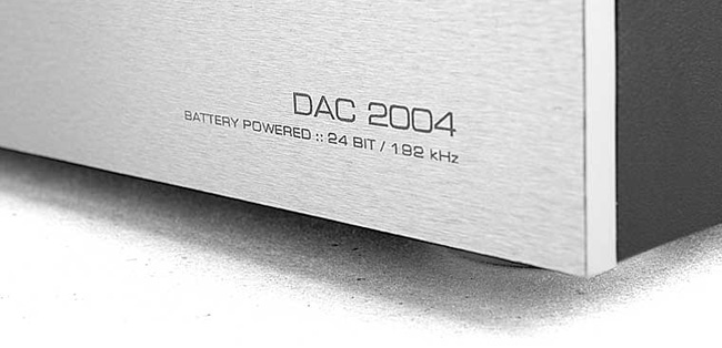
Outer Appearance:
Let’s start from the outside and work our way in. Here you can see the natural proportions of the completely handcrafted DAC 2004. It’s quite a heavy piece of gear at 8.5 Kg (18.74 lbs) and contains more than 400 parts.
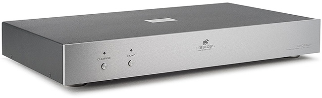
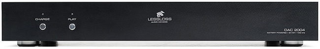
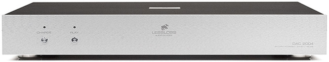
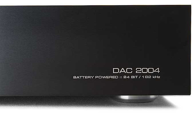
Colors: Silver or Black
The faceplate of the DAC 2004 comes in two colors. Both are anodized and brushed aluminum with laser engraved lettering. At the bottom of the housing you can see the four feet which are individually lathed from solid stainless steel.
Bodywork:
The body of the unit is matte black with a very fine, somewhat sandy feel. This is achieved by electrostatic application of fine granules and then baking them together at high temperature. The silver-colored or dark black faceplate is mounted to the sandy dark black colored body with no visible screws or bolts on the faceplate.
Faceplate Functions:
The two buttons located on the front panel are also individually lathed and are fit by hand directly into the precisely drilled faceplate, without the use of plastic washers, inserts, or the like. The buttons move about half a millimeter when lightly pressed. The actual switching takes place via multiple high quality relays. The audio signal does not travel through these relays. These are to override the internal automatic battery charger if desired.
Laser Engraving:
The laser engraving is carried out by calibrating a wavelength of a laser light beam to react with the material it is to engrave. This is esentially a controlled burning process of the top layers of anodized metal and instantly performs a controlled permanent oxidization of the surface. There will never be any paint weathering off of the DAC 2004. There is no paint to wear off. Both front and back panels are laser engraved.
Design:
The design is purposely kept simple and elegant. The sound quality achieved by the LessLoss DAC 2004 is incompatible with trendy fashion and calculated shelf-life terminology.
Quality, not Quantity:
The decision to laser engrave all of the lettering on this unit allows the designers to delve into detail where standard speedy production processes would yield but a fair approximation. The laser used is only 12 microns wide.
Inlayed Placard:
Because DACs are often the top unit in a system, the design for the top of the DAC 2004 includes a hand-inlayed brushed and anodized aluminum placard. This is a little extra luxury for the sake of beauty.
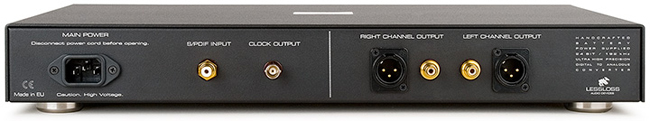
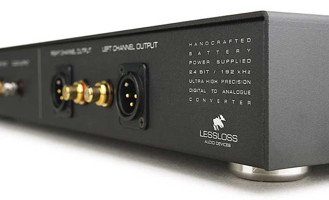
Let’s turn it around.
The DAC 2004 standard features include balanced and unbalanced signal outputs. The SPDIF input and Superclock output are also standard. For some applications, the Superclock can be ordered as Wordclock. 110 or 220 Volts Mains Power are configured by us prior to shipping. If in the future you would want to change the power voltage, it can be easily reconfigured by the owner of the unit.
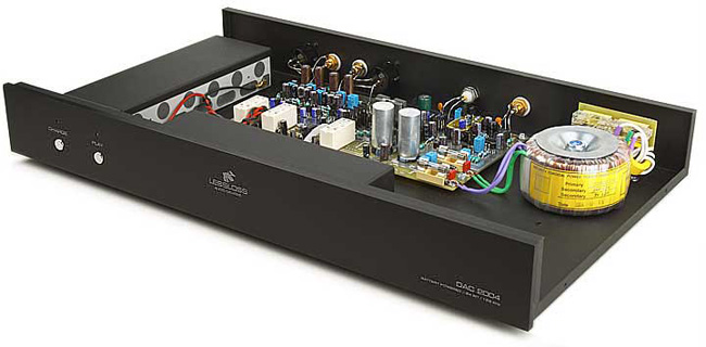
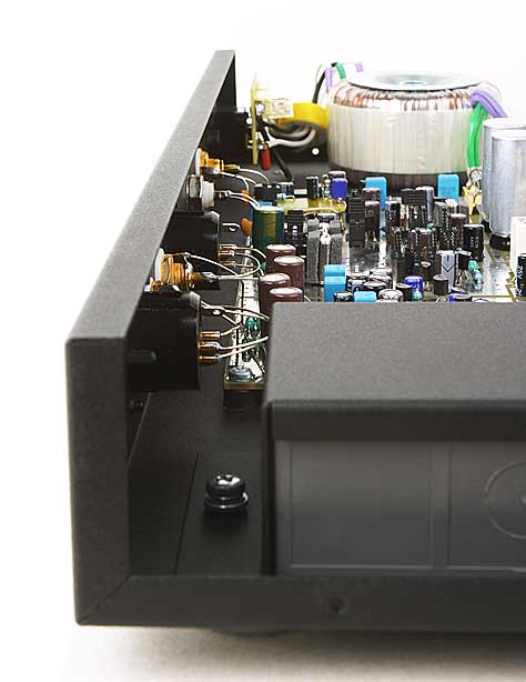
Let’s see the guts.
The LessLoss DAC 2004 has a hybrid power supply. After much evaluation of all sorts of power supply solutions, this is the result: you can’t beat a balanced battery power supply for the audio signal and you can’t beat a well-filtered mains power supply for digital signals. There is power filtering before the transformer, after the transformer, and at every power leg of every IC. No short-cut has been taken anywhere. Even the batteries are selected for their lack of distortion, and then additionally shielded within the shield of the device itself.
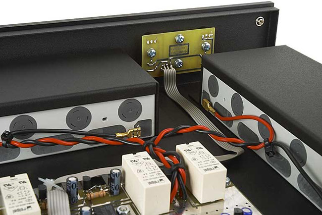
The Batteries:
The rechargeable batteries are quite large and heavy. This is what you’ll be seeing when it comes time to change the batteries (in about two or more years). The shields for the batteries are removeable by two bolts for each battery. You unscrew the bolts, remove the shields and the batteries and then put in the new ones. It shouldn’t take but 10 minutes. The electrical connections are easily visible and immediately obvious.
Usage:
The recharging of the batteries is completely automatic. If you want to charge them immediately, you can press the Charge button. If you want to interrupt the charging process, you press the Play button. A completely automatic charge initiation takes place if you leave the unit on over night. In the morning, you will have a completely charged system and will be able to play music without a second thought. Many users completely forget that this device contains batteries.
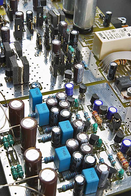
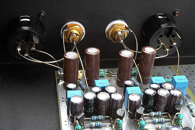
No Mask -- Less Dielectric Distortion:
Note that the LessLoss DAC 2004 circuit is completely maskless: it is not green or red as it would be using today’s standard production methods (robotics). Because of the meticulous production method we employ, we control the entire soldering process and make sure that no unintentional shorting occurs anywhere. This way, we avoid all undesireable dielectric effects of the mask which is always employed in robotic production methods.
Balancing short signal paths with wise circuitry:
The layout is extremely compact. A dual-layer circuit board is employed. Because this device is hand-built sculpture, even the exact dimensions of all of the parts including the losses due to the actual lengths of the various legs are incorporated into the layout. The digital ground is galvanically separated from the analogue ground, and the integrated circuits and other numerous components at the bottom of the circuit board (not visible here) are extremely well shielded from interference. Only top quality parts are used throughout the DAC 2004.
Solid Silver:
The carefully formed, pristine audio signal is carried to the outside of the DAC via solid silver wire, using only the dry air of the interior of the DAC as dielectric. The audio signal passes through only 5 top quality discrete components (7 for balanced) before it exits the device. No capacitors are used in the signal path. This signal path is only ~4.5 cm long to minimize loss and undesired induction.
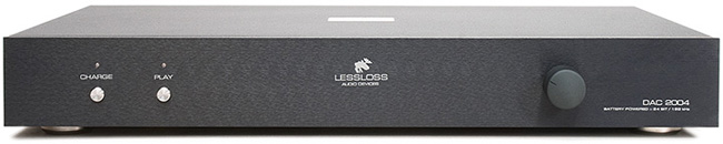
Distortionless Volume Control:
As an option, the customer can choose an integrated 21 discrete position volume control, which is a manual shunt-to-ground volume control located after the DAC chip but before the output stage, resulting in a customized output level at every turn of the switch. This enables direct output to active loudspeakers or a pair of mono amps for the least possible loss in signal integrity.
Hybrid Power:
The DAC 2004 features a hybrid power supply which, together with the galvanically separated digital and analogue grounds, makes the best power supply method available for both the digital and analogue circuitry. The double shielding of the batteries protects the analogue power supply from parasitic frequencies. Because the analogue ground is galvanically separated from the digital ground, distortion is kept to within the limits of the DAC chip.
Thank you for your interest in the LessLoss DAC 2004!
We take much pride in our work, and are always seeking ways to perfect the State-of-the-Art. It would be our pleasure to serve you and share with you the joys of extremely high quality sound reproduction.
The LessLoss DAC 2004 MkII features the following main design attributes:
- Distortionless Volume Control Option Available
- Parallel multibit converters, not the inferior sigma/delta type.
- Hybrid power supply: two rechargeable batteries in balanced configuration, independent filtered power for digital.
- Two galvanically isolated grounds, one for digital, one for audio.
- Unrivalled, non-traditional ultra-low-jitter oscillator with superclock (256F) output.
- 192 kHz sampling rate supported.
- Built in automatic battery charger.
- Over 400 Parts, all top of their class.
- Unusual handcrafted topology.
- Practically immeasurable cross-talk between components.
- Jitter suppression via multi-staged(*) synchronous re-clocking.
- Separately filtered and regulated power supplies to each individual power leg of each microchip.
- 4.5 cm signal path from analogue signal source to external audio jack via solid silver conductors.
- Customizable.
- Laser-engraved stainless steel and aluminum housing.
- Faceplate available in black or silver.
- Introductory Price: 2995 Euros, at your doorstep.
What the DAC 2004 most definitely is:
- Completely handmade, hand-soldered, hand-assembled, tested, and personally cared for.
- An almost completely non-distorting masterpiece of sound electrical engineering.
- The best our knowledge allows us to create.
- Extremely underpriced as a method of marketing without running high debt.
What the DAC 2004 most definitely is NOT:
- Mass-produced.
- A trendy and well-marketed piece of average quality audio gear.
- Distributed through distributors and resellers, raising the price.
Among the several aspects which constitute D/A audio signal converter performance is the converter microchip itself. We carefully studied the available technologies and then, only after narrowing down the choices to only the four theoretically best choices, we built a device for the sole purpose of comparing these four technically best converter chips. In our device, all conditions were the same for all converter microchips.
The method LessLoss used to evaluate the sonic differences between these four microchips was as scientific as possible. We used electrostatic loudspeakers and headphones (almost massless) in order to minimize loudspeaker coloration of the signals. The opinions of highly regarded audio enthusiasts and professionals were unanimous. These tests showed that, at least subjectively, the PCM 1704 was easily the best.
Converter Chip Technology:
We provide two links, one to the manufacturer of the PCM 1704, and one directly to specific data on this microchip.
- Burr-Brown
- PCM 1704
- What the hi-fi magazine Stereophile had to say when the chip was first introduced. (No, we aren’t fortunate enough to be able to buy them in the thousands, and no, we don’t use the cheaper version, the PCM1704U.)
- The PCM 1704 is out of production and represents the end of the era when quality was first on the minds of DAC engineering laboratories. In today’s production, all remaining DAC’s are of the Sigma/Delta type. These incorporate more technologies into one chip, including two channels for stereo, volume control, upsampling, and often even clock oscillators of their own. Production costs have been saved, but the issue of quality of sound reproduction is no longer the primary issue.
Many people do not know that the PCM1704 is classified into different categories of perfection. There is the PCM1704U, which is the least expensive and worst lot. Then there are better ones, which are marked PCM1704U-J and PCM1704U-K at the factory. We would like to stress that the LessLoss DAC 2004 uses only the best and most expensive PCM1704’s. We have chosen the best converter and then use only the best lot of these converters.
There is a fundamental difference between the way parallel multibit converters and the sigma/delta type work. The parallel type use a separate cascade of resistors and switches for each dynamic modulation of the audio signal, whereas the sigma/delta type (or one-bit, as they are also called), rely on a constant comparator to define changes in the audio signal’s dynamic magnitude. Each method has its own advantages and disadvantages.
The main advantage of multibit conversion is that they are theoretically less susceptible to the influences of clock jitter. Their main disadvantages lie in their sensitivity to the influences of heat fluctuation.
The sigma/delta microchips have the advantage of being less sensitive to heat fluctuations, however, they react very readily to any amount of clock jitter.
We compared, using the scientific method of ’same thermal and electrical conditions’, the Burr-Brown PCM1704U-K (parallel), the Analog Devices AD1862N-J (parallel), the Crystal CS43122 (sigma-delta), and the AD1955 (sigma-delta).
Of course, on the theoretical level all of these microchips are superb. Nevertheless, some differences are evident:
- Parallel multibit converters display a distortion spectrum which is more friendly to the ear. This distortion spectrum falls off at a lower frequency than it does in sigma-delta converters.
- At the lower dynamic levels, parallel multibit converters produce a much more esthetic sound than sigma-delta converters.
- Parallel multibit converters produce less sound coloration, and hence the sound is more natural, more lifelike.
- Details and microdynamics are more readily audible using parallel mulitbit converters.
Our empirical tests showed that these differences are indeed audible and that Burr-Brown’s PCM 1704 is the very best converter chip in existence today. Earlier achievements in quality such as the legendary PCM63 have been bettered by the PCM 1704.
A very important issue relating to the quality of a DAC is its power supply. Even a household washing machine has a power supply filter of some sort. Most DAC or CD player manufacturers incorporate a similar or slightly better approach to power supply filtering. Then there are the few who go to the extreme in the "capacitance race". The results are costly, but are they the best possible?
LessLoss, in our goal of achieving the best possible solution, has experimented extensively with the most radical power supply filtering methods. The result of this is a realization of the fact that a real-time power supply filter can never approach the quality attained by the filtering of power using the chemical means of rechargeable batteries, except in the digital realm.
Battery Power Supply:
It is widely known that wide spectrum frequency interference causes intermodulation distortion in any audio amplification system. Purifying the power voltage from this wide frequency spectrum ’trash’ is the goal of the power supply filter. However, in doing so, it also must not bottleneck the current flow to the amplification circuit. Excessive use of capacitance is the traditional solution to this problem. Other extreme solutions include running multiple transformers in series. These are highly costly and impractical solutions. Even when using battery power, some electromagnetic induction of high frequency interference occurs. However, as the amount is small, it is effectively filtered via the use of a small value capacitor.
Advantages of Battery Power:
- A battery is a source of direct current voltage. Using the alternating current of the city mains means not only rectifying the current using a diode bridge, but also filtering it using a large capacity electrolytic capacitor and voltage stabilizer. Even then some amount of undesirable pulsation enters the schematics, and these pulsations include a vast array of harmonics all the way up to the mid-audio bandwidth (about 1 kHz).
- A side-effect of diode bridge rectifiers constantly turning on/off is that this results in undesirable switching interference of a rather wide spectrum. (For this reason there are all sorts of solutions such as "soft recovery" diodes which aim to lessen this problem.)
- Diverse interference enters the mains via sources such as electric motors, microwaves, vacuum cleaners, etc.
- A diode within a diode bridge bears similarity to a diode detector in a radio receiver which turns radio frequency broadcast material into audio signals. If the DAC is to be used near a strong radio signal source, then that parasitic signal can enter the DAC’s schematic.
Relay Circuit:
The LessLoss DAC 2004 uses a multiple relay circuit to charge the batteries from the city mains while the device is not in use. When the user presses the Play button, the relays switch the mains power to the charging schematic off. The relays totally galvanically isolate the audio schematic, including the ground. This frees the DAC 2004 audio schematic from any and all influence resulting from mains interference. This could include your microwave oven, your CD player, or even your local radio station.
The digital section, on the other hand, actually benefits from wisely filtered mains power. In earlier designs, we did incorporate a separate battery for the digital section, but as our newly developed mains filtering solution clearly outperforms any battery solution for digital schematics, we have since abandoned the use of battery power for the digital section. Thus, the DAC 2004 presently employs a hybrid power supply based on a highly filtered mains power supply for the digital section and a balanced battery power supply for the analogue section.
Low Frequency Performance on Batteries?
It is often feared that low frequency performance is hampered by the use of battery power. This is probably due to widespread faulty circuit topology, but certainly not due to the batteries themselves. The DAC 2004 includes two separate batteries. They provide balanced power to the analogue schematics. These are the requirements for the best starting conditions for the cleanest operation of the audio signal schematics.
25x the Theoretically Necessary Current:
The fully Class A battery power supply is constantly supported by 25 times the theoretically necessary current. This results in an operational time between battery charges of approximately 10 hours. When the batteries are low, the onboard automatic battery charger circuit automatically applies a trickle charge to the batteries. You can listen to music non-stop with no interruption to playback. When you want, you can press the Charge button and have the unit mute playback and charge the batteries overnight when you are no longer listening.
By pressing the Play button, the user may choose at any time to prematurely interrupt the charging process and commence playing before the batteries are fully charged. An adequate trickle charge remains, ensuring that the unit never cuts off the music.
Best Possible Performance Over Time:
The charger begins charging the batteries before they run down. This prolongs their life and guarantees the same level of performance from them throughout their lifetime. Indeed, many users completely forget that this is a (partly) battery-powered unit !
Galvanic Ground Isolation:
After every effort is made to ensure that the power supply is as free from high frequency interference as possible, it is important to draw our attention to the inner workings of the schematics themselves. Here, too, because of the potential interaction of the digital and analogue schematics, care must be taken to ensure that we encounter no loss of quality.
Because LessLoss strives to achieve only the best possible solution, care is taken to separate the digital ground from the analogue ground. This is necessary because the digital input portion of a DAC acts as a mini transmitter of high frequency electromagnetic radiation. Not due to design, but due to the inherent properties of the high frequencies themselves.
Electrically and Galvanically Isolated Grounds:
Although many DAC designers are most likely aware of the issues involved in ground contamination by high frequency devices, often times these aspects are deemed too costly to overcome, and, hence, they are either ignored or dealt with in insufficient ways.
As in the concept of battery power, LessLoss seeks the solution deeming the highest quality performance. This solution is found in electrically and galvanically isolating the digital and analogue grounds from each other. Only the rarest DAC design of high cost and commitment incorporate such a solution. Perhaps only two such manufacturers exist.
High Frequency Radio vs. Low Frequency Audio:
The digital input section contains a lowest jitter high frequency oscillator running at several MHz. This high frequency behaves differently than a low frequency audio signal. Every milimeter of distance that such high frequencies travel, and every component or voltage that these frequencies pass by locally on their way around the circuit influence them. In turn, they also influence their surroundings, in effect acting as radio transmitters propagating this signal.
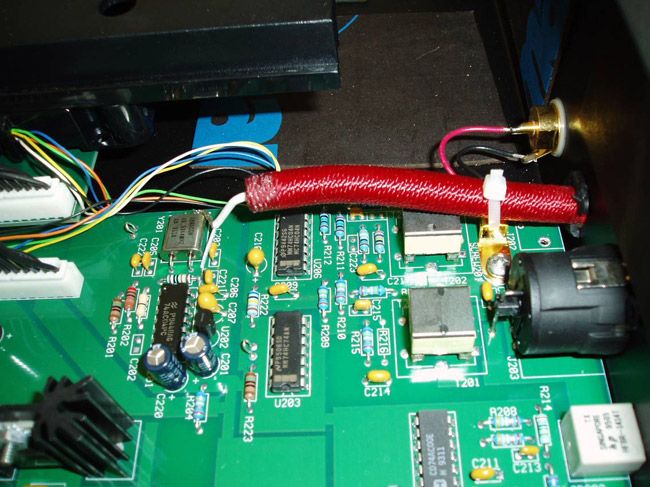
Because this frequency is desired at one, and only one location within the analogue schematics, care must be taken to isolate it at every twist and turn it takes. In the DAC 2004, you can see the transitional section between the digital and analogue schematics clearly.
Please do not confuse our solution with the typical solution of simply putting the digital schematics on their own circuit board and connecting the various circuit boards with a bus-type cable. This is one of the worst Jitter-inducing methods since the bus is an antenna. That’s why one sees various player upgrades with aluminum foil or copper foil covering the bus connections. The best method is not to incorporate this lossey distance into the design in the first place. In the LessLoss solution, both the digital and analogue circuits are on the same circuit board. There is no electrical or galvanic connection between the two, deeming the least ground contamination in the analogue circuitry.
Low-Jitter Oscillator:
The problem of Jitter in digital audio conversion can be understood when you think about Fourier synthesis of a square wave. A square wave is made up of an infinite number of harmonics. So, to generate and to transport something even close to a square wave running at 33.8688 MHz, you need to have completely controlled electromagnetic circumstances well up into the multi-Gigahertz region (for true-to-life quality even up to infinity). It may be argued that timing Jitter is born of the very noise inherent in any electromagnetic space, and this includes a complete vacuum just as it includes a brick and mortar wall.
Realizing this, the makers of the LessLoss DAC 2004 minimize Jitter by means of synchronously re-clocking the digital signal at crucial stages along the path that this highly sensitive signal must travel. This is necessary because no digital signal is immune to the multiple sources of Jitter, which includes the passage of the signal through the noise inherent in the nature of electromagnetic space. The less Jitter, the better the audio. So we want no Jitter. In order to avoid a jittered signal, a low-jitter Master oscillator is required, which is built into the DAC 2004 and located as close to the actual converting components as possible.
Lowest Jitter Clock Oscillator:
The digital input section of the LessLoss DAC 2004 contains an extremely low jitter high frequency oscillator running at 33.8688 MHz. The heart of this low jitter clock is the high quality quartz oscillator. The pure and predictable voltage given to drive this component is key to its practically jitterless functioning.
We use a very high quality analogue quartz sinus generator which is later turned into a square wave digital signal by means of a super fast comparator chip. In this way we achieve the best possible results.
This is Jitter as it might be depicted in a low budget Hollywood film. Highly oversimplified and very black-on-white, this serves to show visually that Jitter is a distortion of the time domain. The best method of overcoming Jitter is to minimize the distance between the oscillator and the converter chip. Any piece of semi-professional digital audio equipment is capable of running in both MASTER and SLAVE modes.
- Digital MASTER means that the device is running off of its own internal clock. The distance between the converter chip and the oscillator is small (internal wiring only).
- Digital SLAVE means that the device is running off of yet another device’s internal clock. This means that there is an external cable bringing the clock signal from the external piece of equipment (the Master) to the Slave. However, this clock signal needs to be extracted from the complex digital signal containing not only the clock but also the changing audio information itself, whose irregularity also introduces jitter.
Perhaps the worst problem with using an external DAC in conjunction with a common household CD player is that the CD player is always the Digital MASTER. Although the LessLoss DAC 2004 outperforms most any DAC even in SLAVE mode, the truly highest performance is obtained while using the DAC 2004 in MASTER mode.
Less Loss Leads to Hi-Fidelity
There is a clock output from the DAC 2004 which enables the user to slave an external digital source such as a CD player or digital sound card to the DAC (provided the soundcard has a superclock 256F input). In this way, the source digital player, or signal provider, is locked to the ultra-low-jitter clock from the DAC. The converter chip (the PCM 1704) is also locked to the very same clock. Because both source and converter are both locked to the same clock, Jitter is maintained at extremely low levels.
In order for a household CD player to function in this way, it must be modified. Only a few commercially available models exist which can run in slave mode. These players are among the most expensive in existence. We provide you with information as to how to do this to an average unit but we will not accept any responsibility for the destiny of your equipment. It’s easy [if you can solder]. There will be no further support offered from our part but we believe that there are plenty of experienced enthusiasts worldwide who would take the time to make this simple yet most effective modification.
Less Loss Leaves No Leaf Unturned:
Because LessLoss is determined to minimize jitter to the lowest of possible levels, we go the extra step to re-clock (also known as quantizing) the digital data to near-perfect timing just a few millimeters before it enters the audio domain. (This image helps depict graphically what this process does -- green is where the signals should be on the graph paper, and red is where the signals are due to Jitter. The re-clocking slides them back into place.)
Sampling Rates:
In SLAVE mode, all Sampling Rates up to 192 kHz are supported.
In MASTER mode, the typical Sampling Rate supported is 44.1 kHz with 33.8688 MHz or 16.9344 MHz outputed to the clock output for slaving a CD player to the device. However, upon user special request, we will accomodate all of the following sampling rates:
- 44.1 kHz
- 48 kHz
- 88.2 kHz
- 96 kHz
- 176.4 kHz
- 192 kHz
Full 24 bit resolution is supported at all frequencies.
Digital Deemphasis is supported at 44.1 kHz and at 48 kHz.
If the unit detects a different signal other than standard audio PCM input, such as Dolby Digital or dts, then the unit automatically mutes. These formats are not supported.
Unique Topology:
Every wire distorts a signal to some extent. Every meter is made up of 100 centimeters. Every centimeter is made up of 10 millimeters. Every millimeter distorts to some extent.
The LessLoss DAC 2004 is designed to minimise every loss possible. The grounding and wiring technique used is much, much more than meets the eye.
Extremely Compact Design
Today’s mass-produced electronic parts such as resistors, inductors, and microchips are smaller than ever. Their small size allows for more compact designs. When constructing a piece of electronic equipment, usually a robot is used. In order to be able to build the equipment, the robot requires certain conditions in the design. Among these is the need for a flat surface area with plenty of room for manipulation. The movements of the robot are standardized.
Robots Are Fast But Humans are Smarter:
Because the goal of the LessLoss DAC 2004 is to aim for perfection in Digital to Analogue conversion, every effort is made to shorten the lengths of all crucial signal paths. Because there are so many crucial signal paths, the design is incredibly compact. The unit is assembled entirely by hand. We solder directly onto the legs of the integrated circuits. In some cases, we actually stack the components directly on to one another. In this way, we really do achieve the shortest possible signal lengths, which no robotic process can possibly achieve.
Another perfection we offer over mass-produced gear is the fact that we do not use a mask on the circuitboard. The mask is a sheet of chemical material added to the top of a circuit board which is usually either green or red. Audiophiles tend to agree that the red composition results in a somewhat better sound than the green type. The reason the mask is brought onto the circuit board is that, when a robot is soldering, the speed and accuracy of this process both have mutual trade-offs and this can result in solder being squirted over areas which might make undesired contact (a short circuit, for example). To avoid this, the mask is used to keep all cases of such occurrences from resulting in production faults.
We go all the way to the extreme and do not use the mask altogether. In doing so, when we solder by hand, we control the entire process and make sure that no unintentional shorting occurs. In this way, we avoid the undesireably dielectric effects of the mask altogether.
What going to the extreme means:
Several of the microchips used in the LessLoss DAC 2004 MkII have legs which are only 1.4 mm apart. We hand-solder these microchips in a very special way, placing parts directly onto them at the most crucial signal paths. This is extremely difficult to carry out successfully and Vil is the only person engaged in this delicate process. Much of the work done on the DAC 2004 MkII is a completely forgotten art these days. The beautiful sound of the DAC 2004 reflects this during every minute of play.
The intricate work put into the hand made DAC 2004 is appreciated by all who listen. When we say shortest possible paths for all crucial signals, we really mean it, as this has a direct effect on the limit of quality attainable.
Good Topology Is More Than Short Signal Paths:
Because everything affects at least something else in audio equipment design, short signal paths are only half of the story. For the very top possible quality, some components must be elevated to avoid dielectric effects, and others must be hyper-shielded. All of these details together make very audible differences and it is the combination of all of this plus our extensive critical testing with both audio material and test signals which results in what was we consider the present state-of-the-art.
HAS THE: Volume Control Option:
We seek the most desirable type of volume control. Would it be a passive preamp? An active preamp? Would it be digital? Analogue? Discrete? Perhaps a potentiometer? What are the losses involved in adjusting the volume level? Can these losses be completely overcome and avoided altogether? Do we really need pre-amps? All of these questions are answered here.
LessLoss now offers a completely distortionless volume control option integrated into the DAC 2004. We would not offer it if we weren’t sure that it represents indeed the best possible solution to the problem. To adjust the pristine signal of the DAC 2004 by any other means is a compromise. We offer you this information so that you may find out how it’s done correctly.
DAC 2004 :: The analogue output is already pristine.
In the DAC 2004, the signals for the analogue outputs at the back of the unit are accessed from the circuit board via very short solid silver wires suspended in mid-air. Between these silver wires and the very output legs of the Burr-Brown PCM 1704 converter chips are only 7 top-quality components (5 for the unbalanced RCA outputs). The purpose of these components is to transform the output of the converter chip from a signal composed almost entirely of current swings to one composed almost entirely of voltage swings. This is known as I/U conversion, or the output stage. In the case of the balanced outputs, the signal is also balanced to provide near-lossless signal transfer over a distance of cable. Please note that the DAC 2004 has absolutely no capacitors in the signal path from DAC chip to external plug.
The other purpose of the output stage is to provide the desired voltage level to the output signal. In home hi-fi applications this is usually 2 Volts RMS, but it can be adjusted during the manufacturing process to whatever desireable level is needed for the given application. This can be any level up to 4 Volts RMS. This involves changing a couple of resistors.
DAC 2004 volume control :: What are the options?
Once the output level is set via the above stated shunt-to-ground resistor, it corresponds to the maximum volume level. Volume controls usually lower the volume level to acceptable listening levels. This can be done in various ways.
In the digital domain prior to D/A conversion.
This is the worst way to control volume level. You not only loose bit-depth of your signal, you also introduce rounding math errors, and ultimately reduce the signal/noise ratio of the actual conversion process. You do not utilize the DAC chip in its best operating conditions, and receive a distorted output signal as a result.
In the analogue domain after D/A conversion.
This is much better. We not only use the original bit-to-bit digital sound signal, we are also using the DAC chip to its full potential and are receiving the closest possible reproduction of the original soundwave which was encoded into the digital domain.
In the analogue domain, we have the following choices:
With active components in the signal path.
All active components need a power supply. Adding components with their own power supplies to an already pristine signal only in order to lower the volume level will inevitably add distortion due to the interference that the power supply carries. Even if the power supply would be ideally clean, then the losses would be equal to the losses incurred by the active components themselves, such as resistors and transistors, which would be placed in the signal path. This could also be a potentiometer used with a linear amplifier.
With passive components in the signal path.
Passive components, such as resistors or transformers, when placed in the signal path, affect both the level and the quality of the signal. No transformer has a completely linear behaviour, especially in the low audio frequencies. Quality discreet switches always have a more exact contact than any type of potentiometer.
With passive components not directly in the signal path, but shunt-to-ground.
This is the best possible method of volume control, and this is the method we utilize in the DAC 2004. This is a passive buffered shunt-to-ground volume control, with 21 discreet positions, with nothing directly in the signal path. This type of volume control does nothing other than switches the very output voltage of the output stage of the DAC 2004. The load on the output leg of the DAC chip remains exactly the same for all volume levels, however the output level is adjusted before the output stage. The DAC 2004 without volume control has an output buffer set at any level the user desires. However, the volume control option allows the user to actively choose the very output level which is desired.
If you use an external processor such as an external volume control (for some reason), you simply leave the DAC 2004 volume control at the highest level of the volume knob. The significance of this is: by using our volume control, it would be the equivalent of customizing the DAC 2004 to a special output level at each click of the dial. This is normally done by changing the value of the resistors used by means of the soldering iron. It is the very best possible volume control, because nothing whatsoever (not even a millimeter of silver wire) is added to the signal path, and in effect you would have not only the exact same sound as without any volume control whatsoever, but you’d have it at the very listening level you desire.
The best solution means, quite simply, the least loss.
No external type of volume control can compete. We have tested with/without the volume control and it is impossible for us to measure any difference between the version with soldered resistors (schematically set output level) and the addition of switching contacts to achieve the variable output signal level. In fact, outboard volume control is worse already by logical conclusion of the following, even if the outboard volume control itself were completely utopian:
Count the minimum number of parts that the signal must pass through: A cable connector at the preamp. A plug at the preamp. Internal wiring in the preamp (using plastics, guaranteed). Internal unbalancing schematics (in the case of balanced signals) at the preamp. Active or passive volume adjustment in the preamp. Balancing schematics. More internal wiring, an external plug. Another connector to the cable which goes to the power amps.
In our solution all of the above are bypassed. You have the possiblity to run direct cabling from DAC to power amps, which, ideally, should be placed directly next to the loudspeakers.
What power amps are compatible?
The input impedance of the amp used in conjunction with the DAC 2004 with volume control option can be anywhere from 10K - 100K Ohm. The input sensitivity can be from 1V - 4V.
Headphones Supported:
Headphone connection.
The DAC 2004 with volume control is perfectly suited for use with electrodynamic headphones from 250 Ohms upwards. For example, the legendary Sennheiser HD650. The original cable will not do because of its low quality and because of its connecting jack. The DAC 2004 has two XLR balanced outputs which should be used with headphones. The wiring schematic is as follows:
DAC output XLR pin 1:
Connect it to the shield of the headphone cable.
DAC output XLR pin 2:
Connect it to the signal "+" (smaller pin) of the HD650 headphone cable.
DAC output XLR pin 3:
Connect it to the signal "-" (larger pin) of the HD650 headphone cable.
The shield of the headphone cable is not to be connected at the headphone end. It should be left floating at the headphone end. The more you shield, the better it sounds.
Output Level?
We can add level to the standard DAC 2004 to accommodate the levels you’d like. Email us and we’ll work out what’s best for you.
Specifications:
When an engineering team is presented with the parts budget for a device they are constructing, they are forced to make many compromises. Even though, remaining within the budget, they choose the least possible compromise, several of these small compromises together result in perhaps a fairly good solution, but by far not the solution that was initially envisaged by the engineers.
LessLoss engineers have the advantage of total freedom in every choice of componentry and design. The DAC 2004 is the exact realization of their initial componentry wish list. LessLoss employs only such components which lead to the best possible solution. Is the price too high to pay for such noble components? At LessLoss, such questions are never raised.
DAC 2004 :: Specifications
- Signal/Noise Ratio: better than -120 dB
- Frequency Response : 10 Hz – 20 kHz +/- 0.2 dB @ 44.1 kHz
- THD+N @ 0 dB: 0.0009% [@ 1 kHz, A weighting]
- THD+N @ -20 dB: 0.006% [@ 1 kHz, A weighting]
- Analogue Out Level: 2V RMS (other levels available upon request)
- Main Power: 220 or 110 V, 25 W
- Batteries: 2 x 12V: 1.8 or 2 or 2.2 Ah
DAC 2004 :: Physical Specifications
- Unit Weight: 8.5 kg
- Unit Width: 44.1 cm
- Unit Height: 6.4 cm
- Unit Depth: 25 cm
- Outer Packaging Dimensions: 60 cm x 40 cm x 40 cm
- Weight Including Packaging: 9 kg
Holistic Philosophy:
The entire LessLoss CD Playback System consists of the following:
- LessLoss DAC 2004 MkII with Volume Control Option
- Rega Planet modified transport, in slave mode to DAC 2004
- LessLoss Dynamic Filtering Power Cables
- LessLoss Firewall Power Filter
This is a lot of stuff, and all of it has only one goal. The goal is preparing the perfect conditions for the mono PCM 1704 (obsolete) converter chips which were the most technologically advanced and expensive to have ever been created. These have never been utilized to their full potential, until LessLoss created the DAC 2004 MkII.
The circuitry of the DAC 2004 MkII is already created with the goal in mind to annihilate all possible Jitter, which is known to be the primary source of distortion in digital equipment. However, this is not the end of the story when seeking the ultimate of all ultimate solutions.
One must at this point view the entire digital playback system holistically, because every other component or cable has influence on the sound as well. Most of this is Jitter related. It is brought about by induction into cables or by feeding power into the gear which contains high frequency noise.
The LessLoss system is completely noiseless, and on this silent backdrop is capable of bringing forth the most pristine analogue signal from the digital domain. We do not offer anything which is viewed as an accessory. Although we strive to lower costs for our customers, they will always find the LessLoss solution to bring about the very best results possible. Other solutions, be they filtering devices, power cables, or digital cables, will always leave something to be desired. That is why our best offer is the holistic offer -- where each and every component works in tandem to yield the very best possible performance of the conversion process itself. And when this is done properly, there is absolutely nothing ’digital’ left in the sound, and one is free from any listening fatigue. Relaxation and pleasure remain the final emotions experienced. Forgiving amps and loudspeakers are no longer needed, as there is no harshness to round out.
At this level, instead of fine-tuning a sound, one simply rejoices in having perfect focus on a dark and silent background.
One of our favorite reactions so far has been "I cannot tell whether my equipment is on or off. I am no longer even concentrating on that. My mind is now free to completely savour the music, which is all I ever intended to do in this hobby from the start. Thank you so much for your achievements, Liudas and Vil!"
COMES WITH Transport: How to Slave a CD Player:
Just about any professional studio gear utilizes the proper Master/Slave relationship between digital source devices and converter devices. We did not invent it. The reason it works is that the master clock for the entire system is as close to the converter chip as possible. This is the single most effective way to accomplish jitter-free audio reproduction.
LessLoss would like you to know why some digital gear sounds bad. The reason is mostly Jitter. To avoid Jitter, you need to make your CD player slave to the DAC 2004. This is a very simple procedure. It is true that some companies charge up to $20,000 for the exact same thing you can do to any $30 player for (almost) free.
How to Slave your CD Player to the DAC 2004
The CD or DVD player needs to have a generator (clock oscillator) of the same frequency which is used in the DAC 2004. We ask that our clients open up their CD player and check what frequency their clock runs on. If your frequency is one of the following, then you can use the DAC 2004 in Master Mode, which means you can run your CD player in Slave mode (the best possible way).
Here are the frequencies you should look for:
- 11.2896 MHz
- 16.9344 MHz
- 33.8688 MHz
If you have any of these frequencies on your clock oscillator, let us know and we will customize your DAC 2004 to run in Master Mode in conjunction with your CD player. Any other frequencies are presently not supported.
In essence all you need to do is desolder and remove the quartz resonator from the CD player, and where one of its legs were, solder on the end of the middle conductor of a coaxial cable (any old coaxial cable will do, but LessLoss also offers ready-made digital cable of the highest quality if you are interested). The shield of the cable should be soldered to the closest ground in the CD player you can find.
To determine which leg contact to connect the cable to, sometimes you can do the following experiment:
- Turn off the CD player. Unsolder and remove the Quartz Oscillator.
- Turn on the CD player. Touch the end of a screwdriver to one of the contacts where one of the legs were. See what happens. Then let go of the contact. Then try the other contact. See what happens again.
- Whichever contact gave the most activity from the player, i.e. motor started turning, changing speeds, the laser motor started adjusting itself, etc. That’s the contact you want to use for the Master Clock cable.
On some players, the experiment described above is not enough, since both contacts seem to have the same effect. In that case, it is highly likely that both contacts will work, but one of them will sound better than the other. This depends on the brand and model of CD player. There are so many of them that it is impossible to list all possible scenarios, but your ears easily show you the way.
That is what you need to do to slave your CD Player to the DAC 2004. The other end of the coaxial cable is to be connected to Clock Output of the DAC 2004. This will lower the Jitter amount at the DAC by a very substantial amount, and it is possible for any audio enthusiast who has experience in soldering to carry this out.
A slaved CD player.
When our clients send us the required photos of their CD player, we draw on them to help them see where and how to connect our superclock signal cable.
Even better results.
It is possible to achieve even better results. For the very best possible digital playback, additional power filtering is necessary. In conjunction with this step, a fully synchronous reclocking schematic can be added into the CD player itself. This requires more expertise in electronics than the average audiophile usually has. Testing equipment is necessary, and building custom schematics is needed. We can carry out this special modification of your CD player. Shipping back and forth is not always the best solution. We can also offer the full customization of a new mass-produced CD player.
Soldering Enthusiasts :: Make a CD Player and Slave it to the DAC 2004
You can get some ideas and inspiration from here. But make sure the quartz frequency is one of the three mentioned above. We have our theory that 16.9344 MHz is the best.
If you have questions please contact us @: https://www.lessloss.com/
< =============================================== >
Weinhart Design is here to earn your trust & future business and always interested in purchasing quality Audio, LP
collections, specialists buying Audio Estates and interested in most quality trades
in’s.
All sales out of California are State Sales Tax exempt. California State Sales Tax of 9.5% applies for items picked up or shipped to a California address.
We accept payments by Bank Wire Transfers without fees and is the only
form of payment on all sales out of the U.S. and Canada. We prefer this
method of payment and also makes shipping to addresses other than
billing OK.
VISA, MC and Papal are gladly accepted within the U.S. and Canada as long as the charge is approved and were shipping to the BILLING ADDRESS and shipping to the billing address on record and adds a 3% fee to cover costs.
Please visit our "ALL NEW & Improved Web Site @ www.weinhartdesign.com
Call me directly in my Audio showroom in Los Angeles weekdays
from 11-4PM @ 310-472-8880 or on my cell including weekends from 10-10PM
at 310-927-2260 and I can answer your questions and help you with all of
your new and pre owned needs.
Making better Sound One
system at at a Time,
David Weinhart
Weinhart Design, Inc.
President & CEO
The Audio and Video Expert
e: [email protected]
www.weinhartdesign.com
2337 Roscomare Road, Studio #1
Los Angeles, California 90077
Showroom) 310-472-8880
Cell) 310-927-2260
No questions have been asked about this item.
Ask the seller a public question
You must log in to ask a question.
Return Policy
Return Window
Returns are not accepted on this item.